

Profile
ENGINEERING HVAC-R VIBRATION ISOLATION: TECHNICAL DESIGN GUIDANCE FROM THE EMBELTON MECHANICAL ISOLATION GUIDES (PART 1 & PART 2)
Vibration isolation in HVAC-R systems is fundamentally a dynamic systems problem governed by mass, stiffness, damping, excitation frequency, and structural response. The Mechanical Isolation Part 1 and Part 2 guides from Embelton provide a rigorous and practical framework for engineers and contractors to design vibration isolation systems with predictable and defensible performance.
Together, the two documents move vibration isolation from rule-of-thumb selection to engineered outcomes, which is increasingly critical in modern buildings with lightweight structures, mixed-use adjacencies, and variable-speed mechanical plant.
-
THE ISOLATION SYSTEM AS A MASS–SPRING–DAMPER MODEL
Every HVAC-R isolation system can be modelled as a mass–spring–damper system:
Mass (m): equipment mass plus inertia base (if used)
Stiffness (k): isolator spring rate or equivalent elastomer stiffness
Damping (c): inherent damping from rubber, cork, or elastomer materials
Isolation performance is governed by the relationship between the natural frequency of the isolation system and the disturbing frequency generated by the equipment.
Effective isolation only occurs when the disturbing frequency exceeds approximately 1.4 times the natural frequency of the isolation system. Below this threshold, vibration amplification occurs rather than attenuation.
-
STATIC DEFLECTION AND NATURAL FREQUENCY
Static deflection is the most practical design variable for predicting isolation performance in spring-based systems. For a simple system, natural frequency is inversely related to static deflection.
As static deflection increases, natural frequency decreases, resulting in higher isolation efficiency. This explains why rubber mounts with low deflection are unsuitable for low-speed HVAC-R equipment, while high-deflection spring mounts are essential for critical and low-frequency applications.
Deflection must always be achieved within the elastic range of the isolator to avoid bottoming-out or instability.
-
DISTURBING FREQUENCY AND VARIABLE SPEED PLANT
The Embelton methodology requires engineers to design isolation systems using the lowest operating speed of the equipment. This approach is critical for variable-speed drives, where equipment may operate for extended periods at minimum RPM.
Designing isolation around higher nominal speeds can place the system in the amplification region during part-load operation, resulting in vibration complaints despite nominal compliance at full speed.
-
LIMITATIONS OF RUBBER MOUNTS AND ANTI VIBRATION PADS
Rubber and pad mounts are limited by their dynamic behaviour. Isolation performance depends not only on deflection but also on rubber hardness and dynamic amplification factors.
As a result, rubber mounts are generally more suitable for:
– High-speed equipment
– Non-critical locations
– Ground-supported installations
They are less appropriate for low-speed HVAC-R plant or acoustically sensitive environments.
-
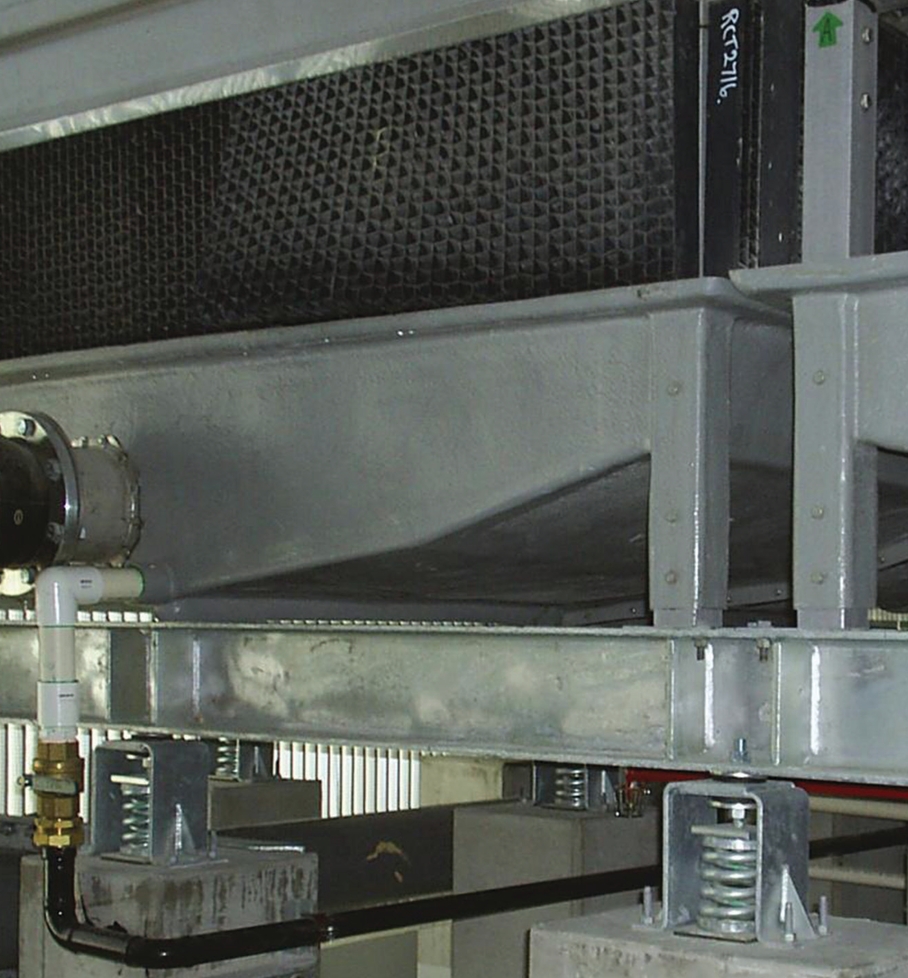
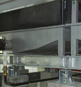
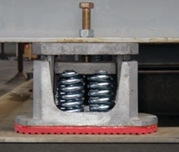
SPRING MOUNTS AND SURGE FREQUENCY CONTROL
Steel spring mounts provide the highest levels of isolation due to their low natural frequency. However, springs introduce surge frequencies that can transmit audible noise if not properly controlled.
Embelton spring isolation systems address this through integrated rubber isolation elements that attenuate audible frequency transmission while maintaining high mechanical isolation efficiency.
-
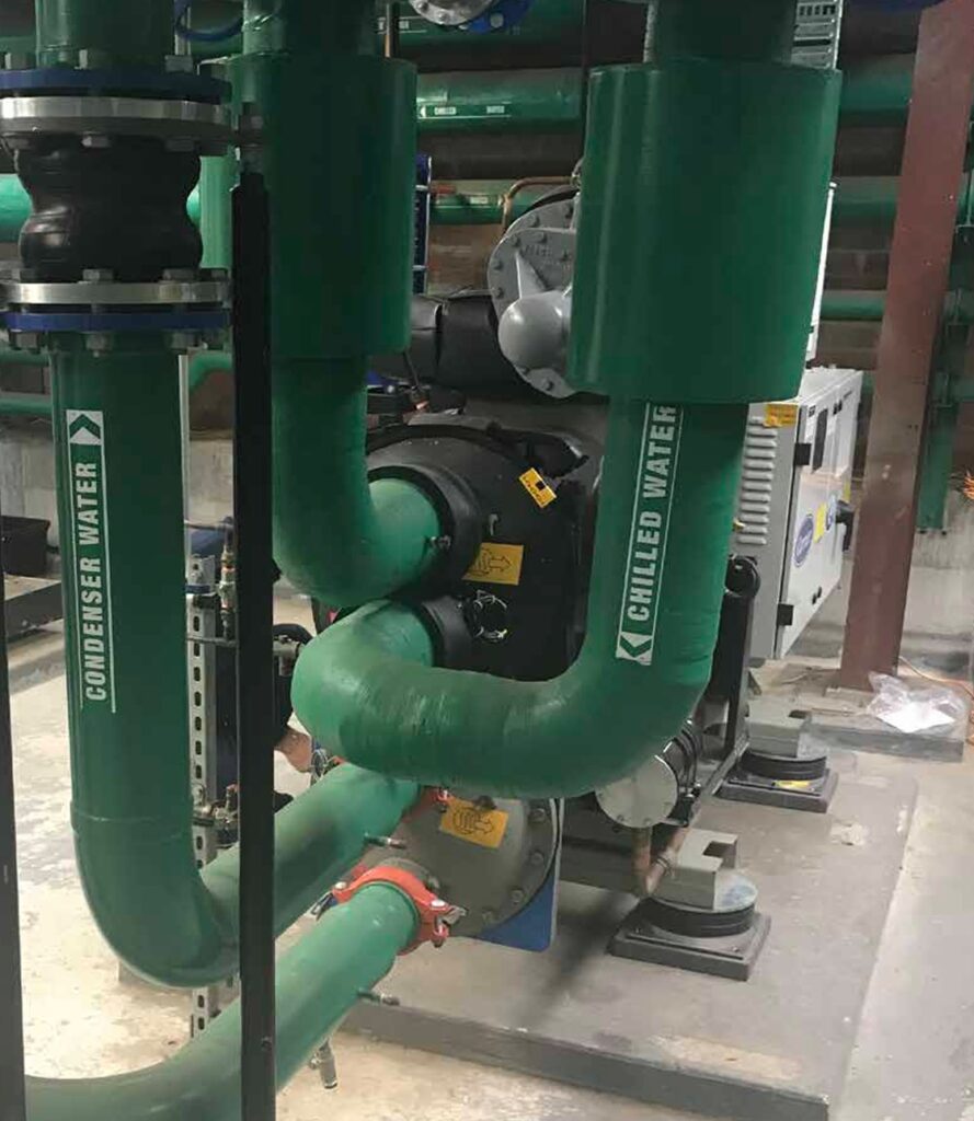
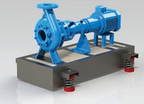
INERTIA BLOCKS AND MOTION CONTROL
High-deflection isolation systems allow movement, which may overstress pipework or flexible connections. Inertia blocks are used to increase mass, reduce acceleration, and limit displacement while preserving isolation performance.
Inertia block geometry, mass distribution, and mount spacing must be engineered as part of the isolation system to avoid rocking modes and instability.
-
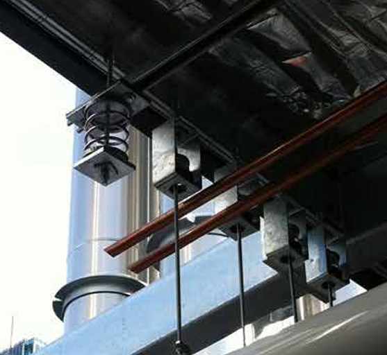
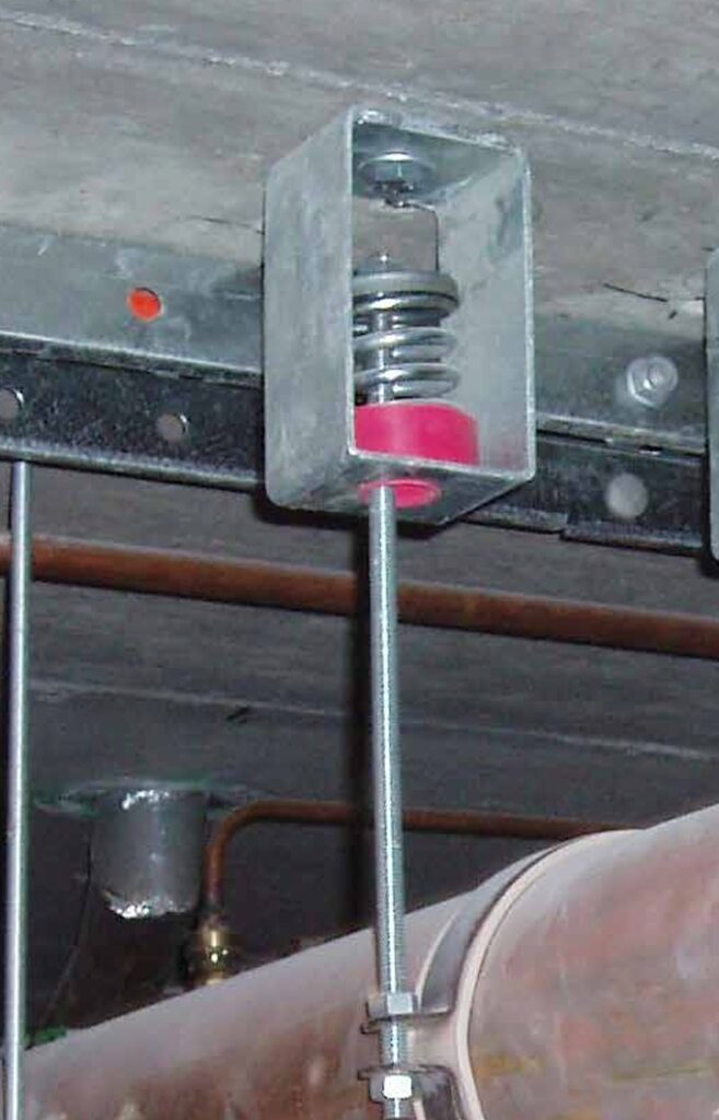
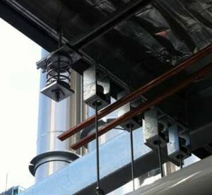
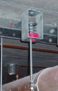
ISOLATION HANGERS AND SECONDARY TRANSMISSION PATHS
Rigid pipework and air ductwork can bypass even well-designed isolation systems. Isolation hangers must therefore be selected with deflection characteristics similar to the equipment mounts near the vibration source.
Isolation should extend for at least 100 pipe diameters from the equipment. Combined spring-rubber hangers are recommended where both mechanical vibration and audible noise must be controlled.
-
LOAD DISTRIBUTION AND INSTALLATION TOLERANCES
Uniform static deflection across all supports is critical. Load uncertainty should be accounted for by applying appropriate safety factors.
Uneven deflection leads to differential stiffness, reduced isolation efficiency, and potential equipment instability. Installation quality is therefore as critical as isolator selection.
-
Selection Charts
The guides provide two key charts to simplify and assist selection process. Please refer to page 4 of Embelton_Mechanical_Isolation_Part_1_May_2019_Digital.pdf
Isolation Efficiency Chart
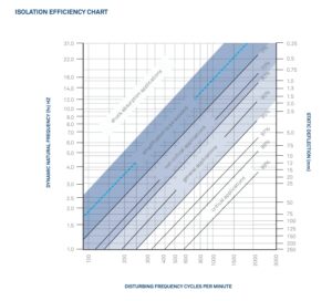
The chart is used to select the correct vibration isolator by linking equipment speed, required isolation performance, and isolator deflection. Engineers first identify the lowest operating speed of the equipment and treat this as the disturbing frequency. From this point, the chart shows the isolation efficiency required for the application and allows the designer to determine either the static deflection needed (for spring-mounted systems) or the dynamic natural frequency required (for rubber and pad mounts). In short, the chart ensures isolators are selected based on engineering performance, not product type, and reflects that spring mounts can be chosen by deflection alone, while rubber-based mounts must account for dynamic behaviour.
Isolator Selection Guide
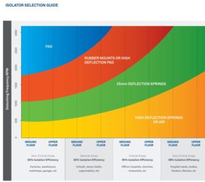
The chart is a practical isolator selection guide that links equipment operating speed, required isolation efficiency, and installation location to an appropriate type of isolator. It recognises that equipment installed on upper floors requires higher isolation than the same equipment on basement or on-grade structures due to structural flexibility. For rubber and pad mounts, the chart accounts for average rubber hardness by using dynamic natural frequency–based values, ensuring more realistic performance expectations. The chart is intended as an initial design guide, with final isolator selection to be confirmed using detailed product datasheets and actual equipment loads.
FINAL HVAC TECHNICAL TAKEAWAY
The Embelton Mechanical Isolation Guides Part 1 and Part 2 treat vibration isolation as a predictive engineering discipline. Part 1 establishes the physics and selection methodology, while Part 2 translates this methodology into practical HVAC-R system design.
Engineers and contractors are strongly encouraged to download and work directly from both Embelton Mechanical Isolation guides and engage with Embelton during design development for project-specific isolation support. It may feel like you are back in university/tafe reading these fundamentals but the Embelton team can walk you through the process.
Embelton_Mechanical_Isolation_Part_1_May_2019_Digital.pdf
Embelton_Mechanical_Isolation_Part_2.pdf